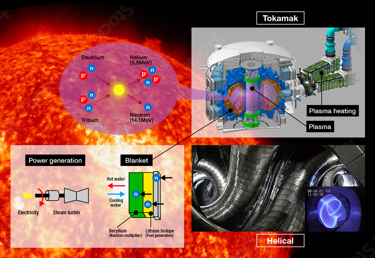
Fusion energy is the ultimate decarbonized energy source: free of CO2 emissions and high-level radioactive waste. It is believed that it can become an intrinsically safe base-load power source, since the fusion reaction is stopped in the event of equipment failure during operation. In addition, since its fuel can be universally obtained from seawater, it can be introduced into electric power systems around the world, and is expected to contribute to energy security. In fusion reactions, which are the source of power for the sun and other stars, the atomic nuclei of the hydrogen isotopes deuterium (D) and tritium (T) overcome the forces that cause them to repel one another and fuse together, at temperatures of over 100 million degrees Celsius. An enormous amount of thermal energy can then be recovered from the neutrons (n) and helium (He) produced. (The energy released from one gram of fuel is equivalent to eight tons of oil).
As a condition for the sustainable occurrence of fusion reactions, it is necessary to achieve a certain level of fusion triple product*, and various pieces of experimental fusion equipment have been designed and developed as shown below. In addition to supporting the design and development of various experimental equipment for fusion reactors, we also participate in the Joint Special Design Team for Fusion DEMO, and are engaged in activities aimed at the early realization of fusion reactors.
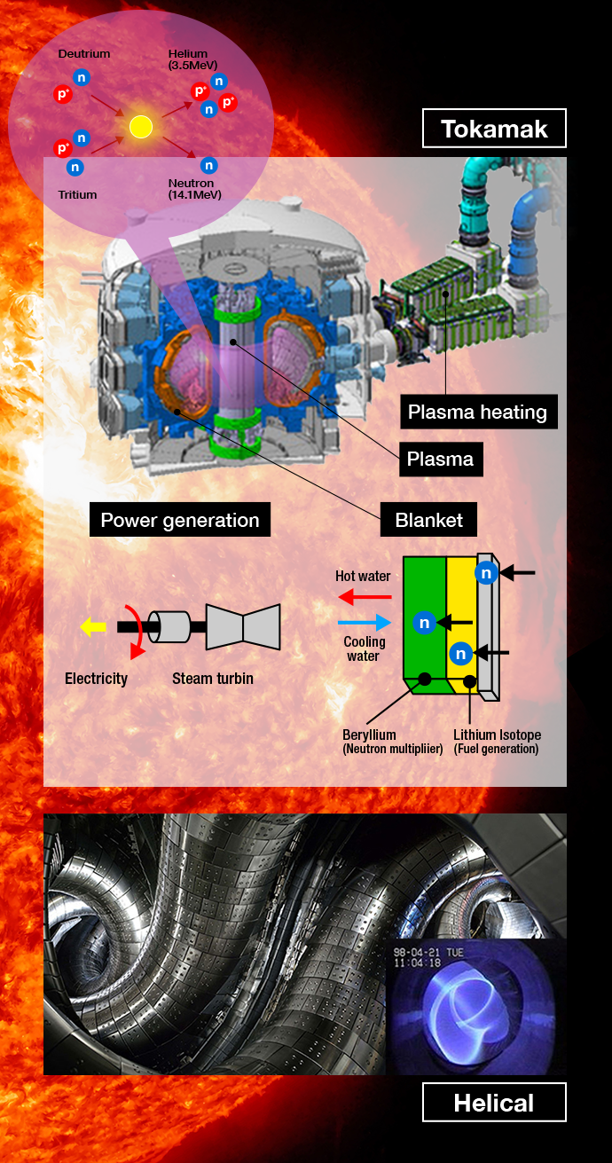
- Tokamak: Plasma confinement in a magnetic field generated by toroidal coils and plasma
- Helical: A spiral-shaped magnetic field generated constantly by a double-helix coil. Strengths in long-term operation
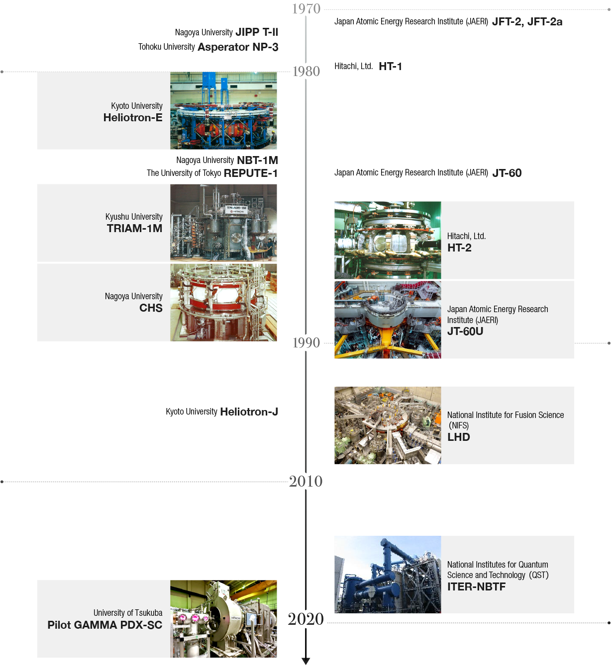
It has already been nearly half a century since we began participating in the research and development for experimental fusion equipment, which is being researched as one of the leading candidates for a new energy source, with research and development being advanced as a national project.
Since the 1970s, we have been involved in the production of fusion equipment in earnest, and have manufactured and delivered numerous pieces of experimental equipment for research and development under the guidance of various research institutes and universities based on electromagnet technologies using our experience with generators, along with equipment technologies (electromagnetic fields, vacuums, control) and superconductivity technologies accumulated at the same time.
ITER is being constructed in France with the participation of seven countries and regions, in order to demonstrate the scientific and technological feasibility of fusion-based energy, which is expected to offer a fundamental solution to the world's energy issues. Hitachi has been contributing to ITER projects, including the construction of key equipment for the 1 MV ultra-high voltage power supply testing facility being constructed in Italy ahead of the heating and current driving Neutral Beam Injection (NBI) for ITER.
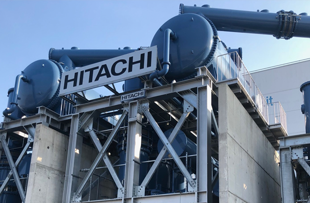
On-site installation of DC generator
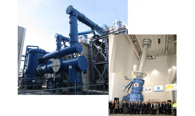
Testing facility under construction in Italy (NBTF)
Above: Near DC filter
Below: 1 MV isolation transformer
Together with the National Institutes for Quantum Science and Technology (QST), Hitachi has developed an ultra-high voltage power supply for NBI, which is required for plasma heating and current drive in the ITER.
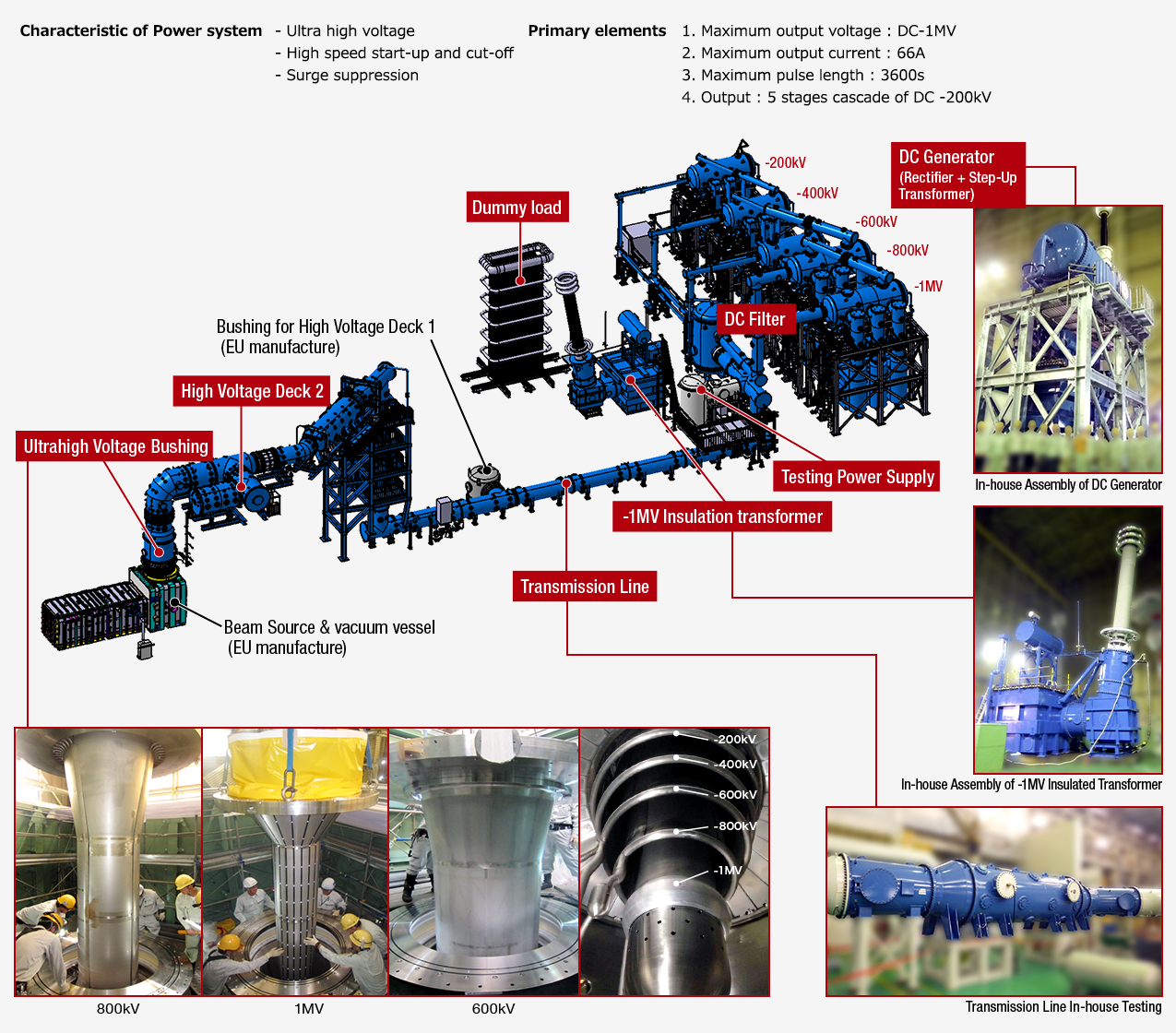
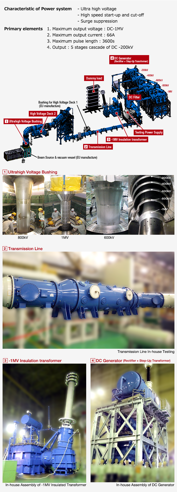
Ultra-high voltage power supply system of NBTF(Neutral Beam Test Facility) (NBTF) (Japan part: red)
A key issue for the transmission line for the NBI device for the ITER is to create a structure that absorbs differences in displacement between the ITER building and the transmission line that may occur during an earthquake. Hitachi developed a relative displacement absorption structure combining expansion joints, laminated rubber, and sliding bearings, and secured the feasibility of the concept through seismic analysis.
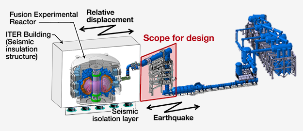
Overview of ITER Building and Transmission Line
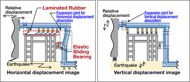
Concept of Relative displacement absorption
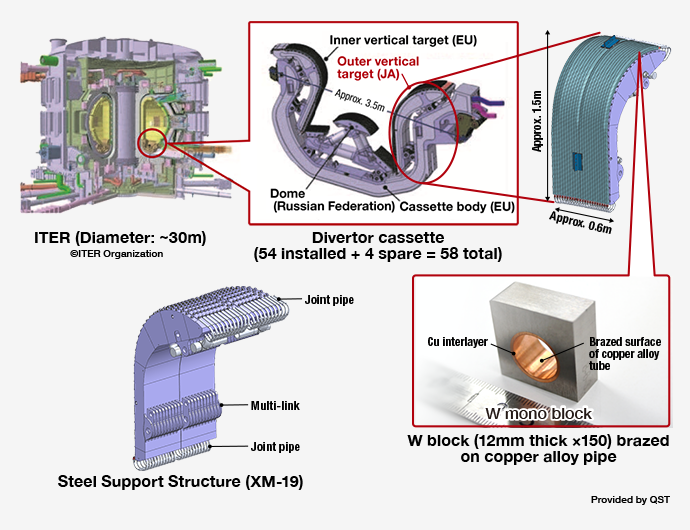
A device called a divertor receives the highest heat load of all in-reactor equipment in the main body of the ITER. It is an important piece of equipment that requires high heat resistance and high precision. We are currently engaged in the production of external vertical targets for divertor cassettes, which are part of Japan's area of responsibility in the project.

Neutral Beam Injection (NBI) is a technology for heating plasma by injecting a high-speed beam of neutral particles into the plasma inside an experimental fusion device. Hitachi's NBI development efforts began in 1977, when we participated in the detailed design of the NBI for the JT-60. In 1985, we delivered an NBI unit for Heliotron-E (Figure 1), which incorporated many of the systems that would become standard in subsequent NBIs, as well as 14 NBI beamlines for JT-60 (Figures 2 and 3), the largest in the world at the time. Since 1990, in order to meet the high-energy, high-power, and high-efficiency requirements for next-generation large-scale equipment, we have been working on the development of negative ion sources and DC high-voltage technologies. In 1995, we introduced NBI for the JT-60U (Figures 3 and 4), and in 1998 and 2000 we developed NBI units for the Large Helical Device (LHD) (Figure 5), and have now been developing and manufacturing NBI equipment for over 30 years.
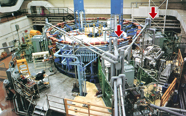
Overview of Heliotron-E NBI
(Photo courtesy of Kyoto Univ.)
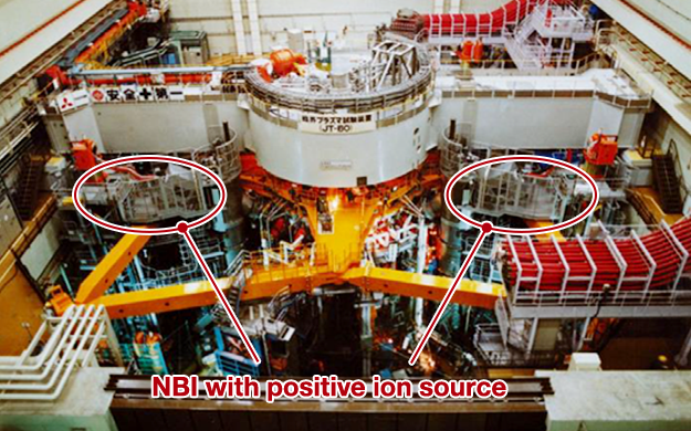
Overview of JT-60 NBI with positive ion source
(Photo courtesy of QST)
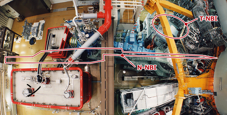
Overview of T-NBI (JT-60) and N-NBI(JT-60U)
(Photo courtesy of QST)
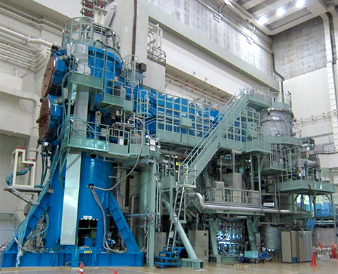
Overview N-NBI beam line(JT-60U)
(Photo courtesy of QST)
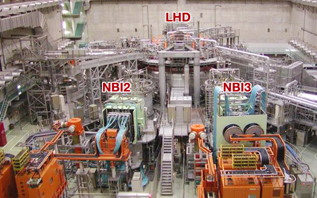
Overview NBI2 and NBI3 for LHD
(Photo courtesy of NIFS)
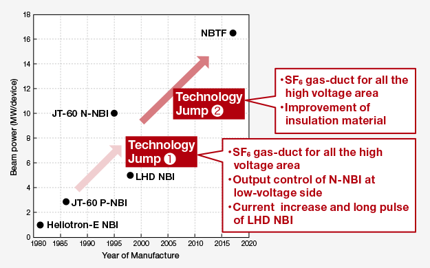
Increase of HITACHI NBI power (Design)
The Plasma Research Center of the University of Tsukuba is constructing an advanced divertor plasma research device, the Pilot GAMMA PDX-SC, as part of the Action Plan for the Development of a Prototype Nuclear Fusion Reactor ("3. Divertor - Development and Experimentation of Divertor-Class Steady-State High-Density Plasma Experimental Equipment"). Hitachi designed and manufactured two pairs of large superconducting coils that form the backbone of this device. The opening diameter of these coils is approximately 900 mm, making it one of our largest superconductive cooling systems for conductive cooling using a refrigerator.
| Superconducting Wire Type | Monolithic, NbTi / Cu |
|---|---|
| Number of Turns | 5,854 turns |
| Rated Current | 236.3 A |
| Central Magnetic Field | 1.5 T |
| Stored Energy | 1.4 MJ |
| Diameter of Warm Bore | 0.9 m |
| Total Weight | 1.9 t |
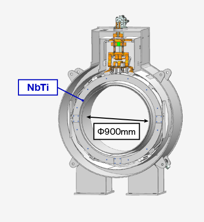
1.5 Tesla - Φ900 bore magnet
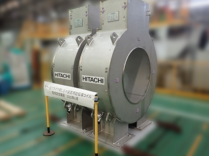
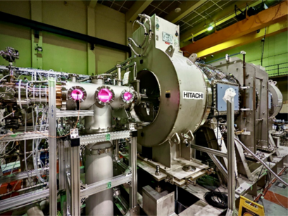
Overview of Polot GAMMA PDX SC
Photo courtesy of Plasma Research
Center, Univ. Tsukuba.
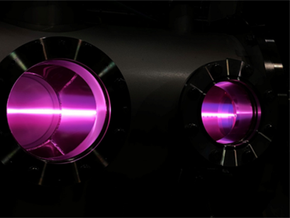
First plasma fired-up
Photo courtesy of Plasma Research
Center, Univ. Tsukuba.
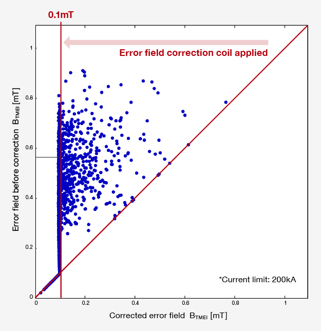
As part of the "1. Superconducting Coil - SC Conceptual Basic Design" component of the Action Plan for the Development of a Prototype Fusion Reactor, together with the QST, we investigated the error field derived from the superconducting coil in the prototype fusion reactor and specifications for an error field correction coil, manufacturing accuracy required for superconducting coils. As a result, we have been able to secure the prospect of relaxing the manufacturing accuracy required for superconducting coils by a factor of 2 to 4 times compared to superconducting coils for ITER.
① Error field evaluation by BTMEI same as JT-60SA※1

② Regularization to suppress required current is applied for current design of each error field correction coils

③ Designed error field correction coils which can achieve BTMEI ≦0.1mT at 95% of 5000 coils with error field
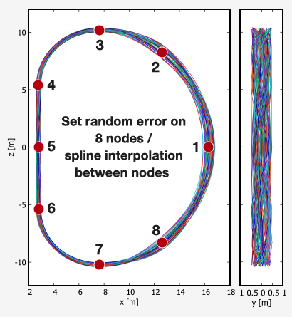
TFC with manufacturing error
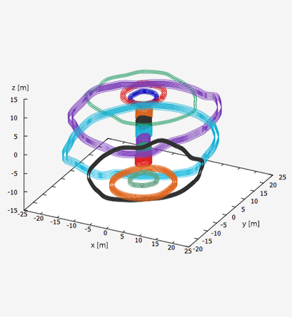
PFC with manufacturing error
※Each errors are emphasized by 100 times
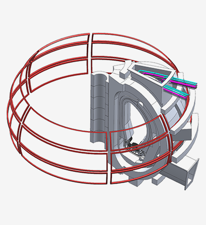
The shape of designed error field correction coils
Hitachi delivered a superconducting coil consisting of a three-layer Nb3Sn (niobium-tin alloy) coil and a three-layer NbTi (niobium-titanium alloy) coil for the National Institute for Fusion Science's (NIFS) high-field magnet test facility. The coil generates a magnetic field of up to 13T (Tesla), enabling conductor performance testing of the coil shape in a high magnetic field.
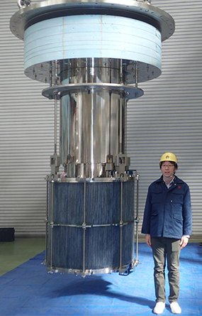
Photo courtesy of NIFS
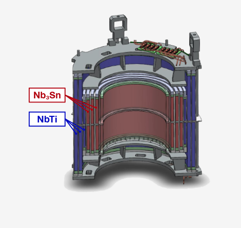
13Tesla - Φ700 bore magnet
(Upgrade to 15T - Φ600 under consideration)
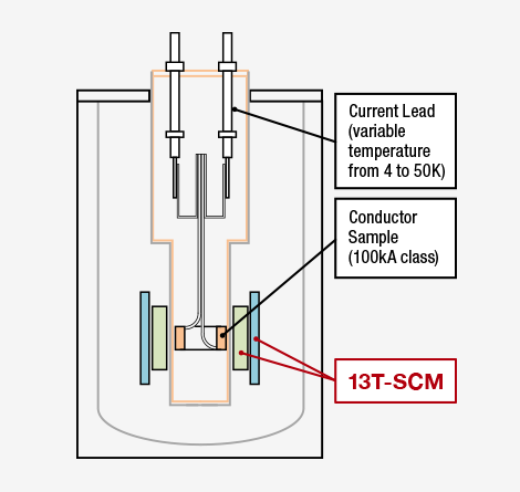
High field test facility at NIFS
QST is conducting performance evaluations of toroidal magnetic field (TF) conductors planned for use in the ITER by simulating operating conditions of TF coils in the reactor. Hitachi manufactured and delivered a solenoid-shaped TF insert coil using TF conductors.
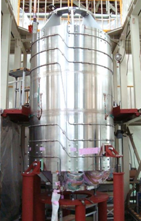
Manufacture of TF Insert Coil※1
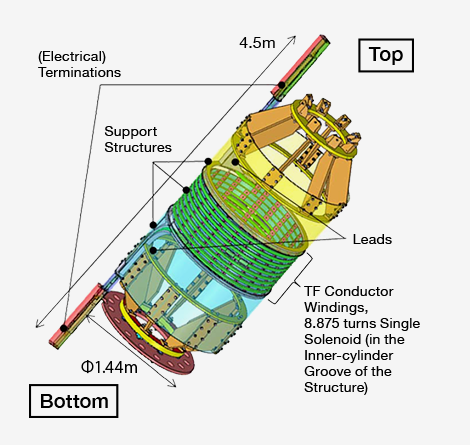
TF Insert Coil※2
courtesy of QST
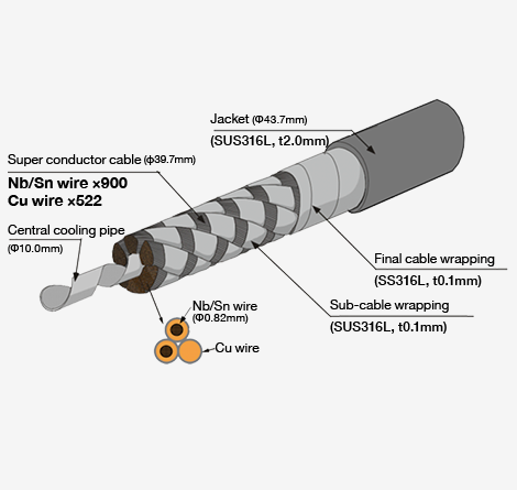
Structure of ITER TF conductor
The LHD is a device designed to confine fusion plasma in a distinctive spiral-shaped superconducting coil, and is based on a unique Japanese idea. Hitachi participated in the construction of the LHD as an overall assembly manufacturer, and since the facility began operation in 1998, has also implemented additional construction including coil cooling systems and internal vacuum vessel equipment, such as a closed divertor and tungsten divertor test units. Going forward, Hitachi will continue to support test operation by providing stable operational maintenance and equipment improvements to enhance performance.
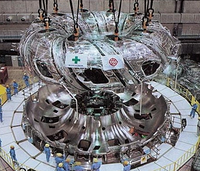
Assembly of Cold Mass
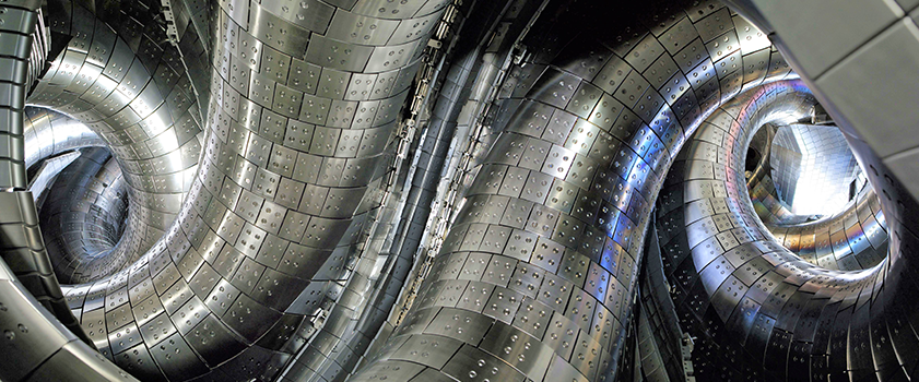
Inside of the plasma vacuum vessel
(Photo courtesy of NIFS)
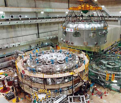
Hanging Cryostat
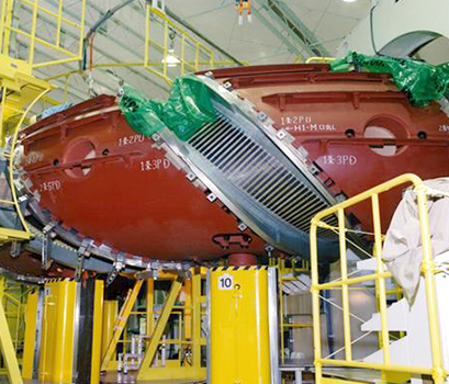
Superconducting helical coil
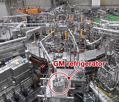
Large Helical Device (LHD)
(Photo courtesy of NIFS)
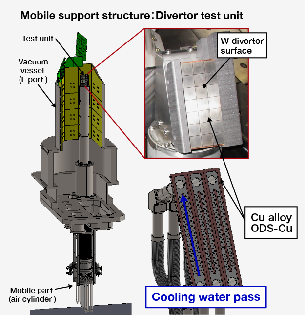
W divertor test unit
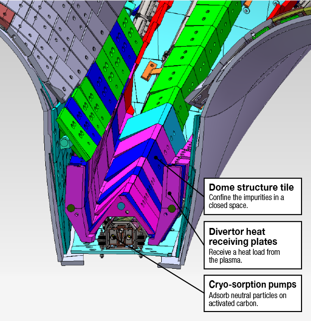
Closed helical divertor